
Traditionally, engineers have communicated design primarily through drawings, sketches, specifications and reports. These types fall into either contracted deliverable documents, typically at project milestones (such as tender drawings and IFC specifications) or engineering advisory information (such as construction phase sketches and reports).
As technology improves however, models are increasingly being used to communicate design rather than drawings and text documentation.

Already, the production of engineering drawings is moving to a process of cutting plans and sections from modelled information. This naturally leads itself to the workflow advantage of transferring those models directly between parties without waiting for drawing production (especially in an evolving design). This is already taking place and there have even been some projects where no drawings are produced at all.
We have a look at three methods of presenting model information below.
1. Data Visualisation
Design data can be presented in many forms including numerical, text and model visualisations. Model visualisations can be the most valuable simply because of the amount of information that can be conveyed in graphical form (a picture is worth a thousand words).
An advantage of having information already modelled is that it can be represented easily with colour or labels.

Information that can be communicated includes:
- Beam types including type or size distribution
- Member Weights and Lengths
- Quantity of members
- Locations of sections (such as level 1 or stability core)
- Utilisation
- Forces such as moment / shear / axial / reactions
- Deflections

Visualisations can be particularly useful to communicate ideas to current clients or other parties not familiar with engineering design. It can also be particularly effective in bids for winning work.
2. Material Schedules
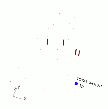
Another advantage of modelled information is that material schedules can be generated from the already existing information.
Sizes, lengths and tonnage can be formatted into tables and charts to clearly convey the information such as in the example below.

3. Animation
Animation can be a powerful tool to communicate ideas and has more impact that a static visualisation. Structurally, it can be used to convey the location of critical structural elements such as the lateral stability cores or foundation systems.
Animation can also convey a sense of the constructability and/or buildability of the proposed design.
The video below shows some animations derived from analysis files as a demonstration of some of the possibilities.
If you liked this information and wanted to find out more, please visit www.structuredparametrics.com. We can help with any of the advantages discussed.
